2013年3月28日 星期四

大型物件列印之翹曲現象與加熱板作用論述

原文出處:http://goo.gl/088nW


這篇文章的許多論點主要是延續原作者的前一篇"warping fundamentals"去思考。特別是,去思考列印的速度、列印物件的尺寸、以及塑料的種類,這些都會是造成物件捲曲的因素。還有一些顯而易見的論點提到,為何加熱板的使用會減少捲曲的現象。
More of the same ‘out loud’ thinking on the issue of warping in this post to follow on from the last post on warping fundamentals. In particular, thinking about how the speed of a print, the size of an object and they type of plastic all effect warping. Also some other obvious points about why a heated print bed helps reduce warping.

接下來要討論列印速度、物件尺寸以及塑料種類對於捲曲現象的影響

The effects of printing speed, object size and plastic types on warping.


透過小型物件的加速列印,似乎顯示這樣的方式可以控制捲曲的程度。這也許是起因於,外部輪廓的部分因時間短暫而來不及冷卻,所以整體的物件在縮短的列印時間下,維持在一個較均勻的溫度狀態下,所得到的結果。
By printing small objects quickly it seems you can limit the amount of warping that takes place. This may be due to the limited time that the outside of the object has to cool and so results in the whole object being of a more even temperature over the short duration of the print.


[上方圖示]印製一個比較、或是慢速列印的物件示意圖
[下方圖示]印製一個比較、或是快速列印的物件示意圖
(左)圖是物件(右)的斷面切片
紅色代表的是物件「受熱溫度分布」的示意圖
Top of image: A large object or an object that is printed at a slow speed. 
Bottom of image: A quickly printed or smaller object. 
The left hand side is a cut away of the solid object on the right.


相同的,上面呈現的圖片適用於說明相同列印速度下的兩個物件;上面為較大的物件,下面是較小的物件。由於大的物件必須花更長的時間去列印,也代表這物件的周圍部分有更長的時間被冷卻,導致翹曲的結果。
Again, the image above also applies if the top object was larger than the bottom and both were printed at the same speed. The larger object will take longer to print and so will have more time for the sides of the object to cool and possibly resulting in less warping. 


或者,當不同的塑料被使用時,上面的物件可以視為高溫加熱成型的塑料(如:高密度聚乙烯HDPE,也就是我們常見的家庭號牛奶瓶),下面的物件則是低溫加熱成型的塑料(如:澱粉生質塑料PLA)。相對於室溫環境,當我們加熱塑料並開始列印,以HDPE和PLA為例,我們比較兩者物件邊緣溫度降低的幅度(相對於物件中心溫度),前者是遠勝後者的。
The image above also applies if different plastics are used, with the top object being a high temperature Tg plastic (Eg: HDPE) while the lower image being a low temperature Tg plastic (Eg:PLA). The higher temperatures relative to ambient (often 25ºC) required to print HDPE will result in the outside edges falling in temperature considerably faster with respect to the centre than compared to PLA.


這張圖說裡包含兩條物件/溫度/位置的資訊
分別表示HDPE與PLA兩種材質,列印物件的尺寸為50mm
0 代表物件的一邊,25 為中心位置,50 是物件的另一邊
Two fictional temperature profiles through the centre of a 50mm
wide object during printing. Zero mm is one side of the object,
25mm is its centre and 50mm is the other side of the object.


雖然HDPE物件邊緣的溫度甚至比PLA物件中心的溫度還要高,它們相對於HDPE物件中心的溫度還是有一大段的距離,然而正是沉浸在這種溫度的蛻變而導致翹曲的現象發生。不同塑料間的擴張係數(expansion coefficient)也是一個關鍵的環節。
Although the sides of the HDPE object are hotter than the core of a PLA object, they are still relatively a lot cooler than the core of the HDPE object. It is this steeper temperature gradient that leads to warping. Differences in the expansion coefficient between the different types of plastic may also play a part.

加熱板與翹曲現象

Heated Beds and Warping.


加熱板顯而易見的,是大型物件冷卻,或者高溫加熱成型塑料等類型的解決方法之一。加熱板的應用被廣泛地推崇,是因為這個裝置的使用所帶來的影響。
Heated beds are the obvious solution to the problem of cool down on big objects or high Tg plastics. The wide spread adoption of heated beds is a tribute to their effectiveness.


加熱板作用下的溫度顯示(右)與室溫下工作面板的顯示(左)
箭頭的方向與大小代表著因外部隆起而向熱核心擠壓,所產生的內應力
A heated bed (in red) is on the right and a room temperature bed on the left.
The direction of the arrows and their size represent internal stresses caused
by contraction of the hot core after the exterior has already become ridged.


不幸的是,就算是用上了加熱板,其功效也是有限的。當一個物件被列印好之後,加熱板(餘溫)的熱效應將會隨著高度而衰退。我猜想這個熱作用的影響,單從物件上方的區塊來看,與加熱板使用的有無是無關的。這些作用於上面切層的內部應力,雖然不至於造成低層(或是其他沒有壓力的切層)在邊緣捲曲,但足以減弱物件的強度來維持固定外型。
Unfortunately it seems even a heated print bed has its limits. As an object is printed the warming effects of the heated bed will diminish with height. I imagine this then leads to the same warping effect in the top section of the object that is present in objects printed with out a heated bed. These internal stresses that build in the top layer would weaken the object even if it is not enough to cause the lower, stress free layers, to curl up at the edges.


這個問題可以從下面的方法來得到改善;從上方持續的以熱空氣吹向物件。一個蓄熱的工作空間或是一個上方架設紅外線燈泡(infrared globe)的環境。然而,一般的商用的印表機如果無法使用可溶解的(dissolvable)支撐材(reprap系列正在測試中),就原作者的理解與想像,現行的使用配合這樣的加溫環境處理還是有其限制,例如脆弱的懸挑部份,以及黏附在外圍像鼻涕的部分。一個解決這些垂滴的方式,就是搭配大量的風扇使用,但是這樣一來就又會回到因為失溫而翹曲的問題*(注)。
This problem could be solved by streams of hot air blowing from above, a heated build chamber or even an infrared globe above the print bed. However, with out the dissolvable support material used in commercial printers (work in progress for reprap's) I imagine this will also have its limits as slight overhangs or teardrop through holes begin to slump on larger objects. A simple solution to slumping is to strap on a lot of fans, but then you would be back at square one with the warping problem*…


*注記:如果能有一種方式可以分析一個3D物件,並且指出哪邊最容易發生這種殘料滴垂的現象,那真的就太美好了;我們可以針對這個高風險的列印區塊,我們透過控制噴頭旁的風扇來導入室溫的氣流。這樣將可以同時兼具一個加溫的工作區塊,以及避免高溫而讓塑料滴垂的現象。不過這還只是一個構想~
* Just as a side note: What would be really nice is if there was a way to analyse a 3d object and determine where slumping is most likely to occur. Then throughout the print a fine jet of room temperature air aimed at the print nozzle could be turned on or off as the print head prints the layers above these 'high slump risk zones' . You might be able to get away with having an elevated build chamber temperature and reduce slump at the same time. Just a thought.


以緩慢控制的方式降溫,也是一種列印大型物件時,有效大幅減少翹曲現象的方法。相較於加熱板的完全加熱狀態,到完全停止加熱,取而代之的是以一種逐漸降溫的方式(比方每分鐘減低攝氏2-3度,直到降至室溫為止)。這樣做的目的雖然可能可以減少捲曲的現象,但是原作者表示他還沒有認真試過。(小編:這真的有效!)
It may also be possible to greatly reduce warping by having a slow controlled cool down such as used when casting large objects. So instead of the heated bed switching from 'full on' to 'full off' there could be a gradual decline of 2 or 3 degrees per minutes until room temperature is reached. This might aid in reducing warping but has not been tested as far as I'm aware.


有一點應該注意的是,加熱板應該要能夠提供強力的附著性,特別是它的表面與塑料底部第一層的接觸。我之所以會關注這點是因為高溫狀態下,化學分子之間的接觸會更加劇烈(低溫熱熔塑料的表面張力);長時間作用下,塑膠會熱熔於表面同時達到像液態依樣的包覆與延展。(更多訊息請參考這一篇,原作者撰寫的文章提到"塑膠就像膠水")
It should also be noted that the heated print bed seems to also allow for greater adhesion between the print bed surface and the first layer of plastic. From what I can gather this is due to an increase in intermolecular contact brought about by the higher temperatures (lower molten plastic surface tension) and the longer time frame were the plastic is molten at the surface and so can spread (wet) more. More info.


不論如何,我希望這些資訊對於RepRap社群的新成員能有所幫助。如果我省略了甚麼部分或是哪些部分有誤,請務必讓我知道。(原作者相當客氣)
Anyway, I hope those new to the reprap community find this helpful. If I missed a few things or something doesn't seem quite right please, by all means, let me know.

關於原文作者Richard,是一位在澳洲墨爾本攻讀材料工程的博士生。在他這篇原文下方的首則回應,對於上述的內文有多處的辯證與補充,提出的論點相當有趣,順手翻。


我真的認為這種理論性的分析對於解決翹曲的問題而言是很重要的。我寫了一篇簡短的分析(應該也要多闡述一些細節才對)。寫這篇回應的同時,我思考更深入關於造成翹曲的因素,顯然我的分析與你的重點不同;這讓我得到不同的結論,所以我想,在這邊留下這訊息是重要的。
I really think this kind of theoretical analysis is important to solve the warping problem. I wrote my own short analysis in this thread: http://forums.reprap.org/read.php?1,55300 but I might do a more detailed write up as well. Writing that post made me consider in more detail the causes of warping. My analysis differs in important ways from yours, though, which leads me to different conclusions. So I feel it's important to comment here.


我想我們兩者都清楚,翹曲發生的關鍵在於切層溫度的收縮(thermal contraction)。用計量的方式分析,我們可以想像不管再小的任何線段,都具有兩種不同的長度;高溫時的長度(Lh)以及低溫時的長度(Lc),而且每種塑料都是Lh>Lc。
 It's clear to both of us that the key factor when it comes to warping is the thermal contraction of layers. For a qualitative analysis, we can imagine that any short segment of filament has two lengths: The length when hot (Lh), and the length when cold (Lc), where Lh > Lc for any particular filament. 


任何時刻只要你在一個冷的塑料上面列印上一條熱的塑料,你必須思考四個長度的變化。第一個長度是剛列印出來的塑料(L1h),第二個是這個塑料冷卻後的長度(L1c),第三個是舊的塑料在剛被列印出來時的長度(L2h),以及舊的塑料冷卻後的長度(L2c)。
Any time you print a hot filament on a cold one, you have four lengths to consider: The length of the hot new filament when freshly printed (L1h), the length of the new filament after it has cooled (L1c), the length of the old filament when it was freshly printed (L2h), and the length of the old filament when it has cooled (L2c). 


根據溫度收縮,我們知道 L1h > L1c 且 L2h > L2c。
Due to thermal contraction, we know that: L1h > L1cL2h > L2c 


我們也知道,熱的塑料是列印在冷的塑料上,所以這意味著後面兩者的長度相等:L1h = L2c
But we also know that the new, hot filament is printed on the old, cold filament. This forces their lengths to be equal: L1h = L2c 


這是造成問題產生的癥結。當物件冷卻之後,因為 L1c < L2c 所以物件捲曲。不均等的冷卻並不至於導致翹曲,列印的哪一部分先冷卻並不重要。重要的是列印出來的塑料是堆疊在冷卻後的塑料上面。一個緩慢的冷卻行為不該與快速冷卻有任何的差異才對。
That's where the trouble happens. When the object cools, L1c < L2c, so the object warps. Uneven cooling does not lead to warping; it doesn't matter which part of the printed part cools first. What matters is that hot filament is deposited onto cold plastic. A slow cool down shouldn't be any different than a rapid quench. 


假如你在均溫下拿一個沒有翹曲的物件,然後對其增加一個特定變幅的溫度(在任何的增溫速度下,比方一個漸變的高溫差),這物件將會彎曲。但是當你讓物件回歸均勻的溫度時(不論降溫的速度如何),它將會回到原本的形體。現在面臨的問題是,剛被列印出來的物件是一個尚未捲曲的狀態(因為它定形在一種不均溫的狀態);當它被帶到一個均溫的環境下,它就會翹曲了;這件事情變換得快或慢並不重要。例外的狀況是,假如溫度的變化大到足以造成相位的改變,這樣的前提下,內部的結構將會在這個過程之後改變。
If you take an un-warped object at a uniform temperature, and impose a temperature gradient on it (at any speed), it will warp. But when you return it back to uniform temperature (at any speed), it will return to its original shape. The trouble is that a RepRapped part is an un-warped object at a nonuniform temperature. When it is brought to a uniform temperature, it warps. It shouldn't matter how quickly the transition happens. The exception is if the temperature change is high enough to cause a phase change, in which case the internal structure will be different before and after the process. 


現在來思考列印速度與物件尺寸對翹曲產生的影響。Lh 與 Lc 的差異是與溫度變化呈一個比例關係的(Lh = Lc + a dT)。假設一個極度快速或是非常小型的列印,所有的塑料是以急速堆疊的方式(沒有時間去冷卻),因此此時的 dT = 0,而且沒有翹曲的現象發生。反之,在一個極度大型或是非常緩慢的列印狀態,先前列印的塑料總是在新塑料列印堆疊之前,冷卻到室溫下;此時的 dT = max(材料熱縮的最大值)。
Now to consider the effect of print speed and object size on warping. The difference between Lh and Lc is proportional to the temperature change (Lh = Lc + a dT). For an infinitely fast or small print, all the filament will be deposited instantaneously with no time to cool between layers, so dT = 0, and no warping occurs. For an infinitely large or slow print, the old filament has always cooled to the ambient temperature by the time the new filament is laid down, so dT = max. 


一個列印的常態既不是非常快也不是非常的慢,因此有兩個關鍵的因素要思考;物件是從表面冷卻(熱傳遞與熱輻射),以及熱量的擴散(熱傳導)。熱量是由新堆疊上來的塑料所產生的接觸面,經由新塑料的本體傳遞到舊塑料的冷卻表面。
For a print that's neither infinitely fast nor infinitely slow, there's two important factors to consider (that I can think of). There's cooling from the surface of the part (convection and radiation) and thermal diffusion inside the part (conduction). Heat is added from the surface, in the form of freshly deposited filament, and then conducts through the body of the part toward the cold surface. 


這並不是溫度遽變導致翹曲的發生。這裡提到的非均質溫度指的是物件的邊緣區域,熱的塑料是被列印在冷的表面上;然而在加熱板中心區塊,熱的塑料是列印在熱的塑料上。這樣的現象意味著邊界的部分將會有最大的應力;物件內部則是最不售應力影響的,因為 dT 在中心是最小的。然而,就算物件沒有溫度上的漸變溫差(舉例,假如它是一致的冷,比方慢速列印的狀態),翹曲的狀況還是會發生(因為新列印的塑料是熱的)。這僅是單純的考量,然而翹曲的應力甚至會貫穿整個部分。
It is not the steepness of the temperature gradient that leads to warping. What this non-uniform temperature means is that at the edges, hot filament is printed on cold plastic, whereas at the center, hot filament is printed on warm plastic. That means that the warping stresses will be highest at the edges, and less at the center, because delta T is less at the center. However, even if there were no temperature gradient in the object (ie, if it were uniformly cold, as in the case of the slow print), warping would happen because the fresh filament is hot. It's just that in this case, the warping stresses will be even throughout the part. 


性質上地說,這兩者之間並沒有過大的差異;一者是均衡的捲曲(所以它可能是導致底部產生一個拋物線形變的原因),另一個則是不均衡的捲曲(可能是一個更接近於四度曲線,在邊緣處有一個落差的翹曲);不論何者,它們都導致物件的翹曲。
Qualitatively, there's not a big difference between these two cases; one warps evenly (so it would probably form a parabolic shape at the bottom) and one warps unevenly (so it might be more of a quartic curve, with the steepest bend at the edges). But they'd both warp. 


就我的想像與理解,一個物件是可以被列印到一個非常高的程度,只要搶在加熱板的作用衰退之前。加熱板通常都是比物件本身來的寬,熱傳導的增加和溫度的提升是從物件的邊緣開始,然而減少對流的冷卻效應也是。假如這樣的現象變成一種困擾,那麼當列印推升到某一個定點高度之後(這個定點是承受整個結構改變的基礎點),只要將加熱板的溫度視物件的高度作提升,如此就可以讓上部的表面維持一個恆定的溫度。然而,這樣可能需要一些非常尖端複雜的軟體。
An object would have to be very tall before the effect of the heated bed could really wear off, I imagine. Because the heated bed is generally wider than the object, there should be warm convection currents rising and warming the sides of the object, reducing convective cooling. If it became a problem, then up to a certain point (the point where the base of the part would undergo a phase change), the temperature of the heated bed can be increased as the object gets taller, so as to maintain a constant temperature at the upper surface. That would probably take some sophisticated software, though. 
Jacob

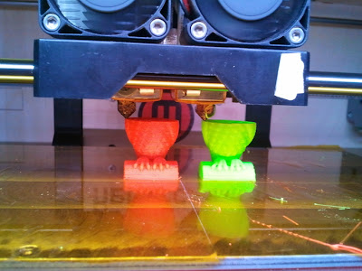
讓你的Replicator雙噴頭機器同時列印兩個相同的小物件

原文出處:http://www.thingiverse.com/thing:23792
讓你的Replicator雙噴頭機器同時列印兩個相同的小物件
Dual Extrude Both Extruders at Once for Replicator

[微hack]透過簡單的Script改寫雙噴頭的Gcode
這是一個Script,讓你的機器同時列印兩個相同的小物件。[1.1]

[1.1]Script下載之後會看到三個文件檔

工作原理說明
這個script基本上是改寫噴頭的路徑,將原本指令裡單一個噴頭(E000)的部分轉換成雙噴頭(A000 B000);Dimension/5D(Skeinforge路徑引擎裡的一個選項)在此設定是必須被開啟的。
How it Works -the script basically changes every extruder movement for 1 extruder ( an E000) to an extruder control movement for both extruders (A000 B000). Dimension/5D has to be enabled for this to work.

工作流程說明
指定下載的[start.gcode]取代預設檔案,之後將GCode路徑設定運算出來。
將運算出來的GCode以[bothext.vbs 或 bothext_win7.vbs]跑過一遍。(視你的作業系統,擇一)
開啟 ReplicatorG 軟體,將這個改編過的 GCode 轉出,送到 Replicator Dual 機型列印的。
Work Flow -Generate gCode as per usual but use start.gcode with Dimension based Anchor.Run the generated Gcode thru the script.open the gcode with ReplicatorG and print.

需要變動的設定
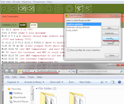
建議先複製[Duplicate]一個Profiles,以本圖為例(DualExtrudeMode)
先點選[Locate]找出要置換檔案的位置

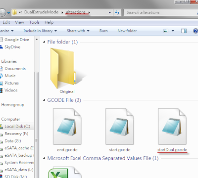
將下載的[start.gcode]改名變更為[startDual.gcode]
放置位置為上述位置裡的[alterations]資料夾
然後按下上圖裡的[Edit]進行以下編輯

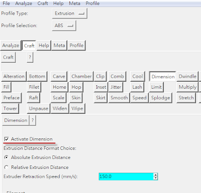
Skeinforge 設定裡的[Dimension]選項必須被開啟(Activate Dimension)[1.2]
Settings that need to be changed -dimension needs to be turned on in Skeinforge so the we get an E000 code for extruder movements.
[1.2] Dimension 選項必須被開啟(Activate Dimension)

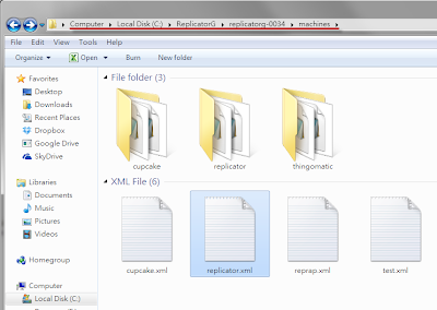
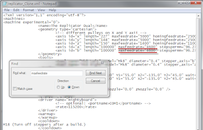
對[ReplicatorG / Replicatorg-0034 / machines]資料夾裡的[Replicator.xml]檔案進行編輯[1.3a],將 id=a 與 id=b 後面的[maxfeedrate]數值,由 1600 改為 4600[1.3b],如此一來 skeinforge 就不會在每次你運算GCode時大發脾氣。作者說他任意的將4600這個數值填入,假如有誰知道更適合的數值請告知他一聲。
the ReplicatorG34/machines/Replicator.xml file needs to be changed so the maxfeedrate on A and B is 4600 instead of 1600 so skeinforge does not throw a fit everytime you generate gcode. I arbitrarily picked 4600- if someone knows the proper number let me know. 

[1.3a]以notepad.exe 對[replicator.xml]檔案進行編輯

[1.3b]將 id=a與b的maxfeedrate數值從1600改成[4600]

在 skeinforge 程式的[alterations]分頁裡,移除[remove Redundant Mcode]的勾選,不然第二個噴頭的預熱功能將會失去作用[1.4a]。之後將原本的[start.gcode]位置[1.4b],改對應為剛剛放上的檔案[startDual.gcode]
-in skeinforge alterations tab- remove Redundant Mcode needs to be unchecked otherwise the warmup of the 2nd extruder gets removed.
[1.4a]移除[remove Redundant Mcode]的勾選

[1.4b]更換對應的起始指令碼為[startDual.gcode]

你可以擇一而做:
-讓機器指定使用下載的[start.gcode]
-或新增一個[profile]並設定讀取使用下載的[start.gcode]。[1.5]
-或使用[use default start/end.gcode]選項,再去設定你要用哪個版本的[start.gcode]。
you can either: -use the dimension based start.gcode all the time-create profile that uses it the dimension based start.code-use the "use default start/end.gcode" setting in the generate print dialog to control which one you use .
[1.5]取消勾選 use default start/end.gcode 選項
系統才會去讀取特製的[startDual.gcode]設定檔

下載的資料夾裡面有兩個版本的 Gcode 轉檔指令集,一個是給 XP 作業系統,另一個是給 Vista 和 Win7 作業系統[1.6a]。
在 Win7 版本你必須在跑這個指令集前,將每次要轉的檔案指定所在的路徑位置[1.6b]。想偷懶的話,就把檔案放在C:\下吧![1.6c]
之後會跑出一個剛轉好的檔案[1.6d](如果有誰知道可以減少這個步驟,麻煩通知原作者)
-there are two version of the gcode conversion script
- one for XP another for Vista and Win7
- in the Win7 version you need to edit the script to change the file name that is being converted each time(if someone has a way to do a file dialog like the XP version let me know) 
[1.6a]畫面下的兩個檔案,視你的作業系統選擇使用
[1.6b]Win7的版本必須編輯內部的指定檔案路徑
[1.6c]偷懶的方式,可以將檔案直接放在C:\下
[1.6d]轉好的檔案會出現在同一個存放位置

[檔案輸出前的最後確認]請確認有下面兩行指令列
M104 S220 T1 (二號噴頭加熱)
M6 T1 (二號噴頭預熱等待)
T1 代表的是第二個噴頭,也就是左噴頭


起始的Gcode裡面有一些機關是原作者還在嘗試的。加熱板看起來似乎是拖慢進度的關鍵,所以我在start.gcode裡面就把加熱板啟動的程序先排入了。我不用慢慢等程序跑到加熱,我啟動後直接讓它加熱到我預設的105度,然後歸零的動作完成後,它會被迫冷卻到100度再被加溫到110度而不需要長時間的等待。(作者不認為加熱板在列印前必須被加熱到110度)之後我們必須等待噴頭被加熱,直到一切開始列印運作。
the startup gcode also has some warmup tricks I am currently testing. The bed seems to be the slow spot in the warmup so I turn it on at the start of the script. I don't wait for it to be warm at that point simply turn it on, I use 105 degrees in case it is already warm. Then once the homing is done. I wait for it to warm to 100 then turn it to 110 without waiting(I don't think the bed has to be at 110 before we start printing). Then the extruders get turned on and we wait for them to be ready.

已知的問題
配套鎖定的[start.gcode]需要下一番功夫設定。
Mac 和 Linux 在現階段不好意思,轉檔編譯器沒辦法直接拿來用喔!(如果有誰想轉譯成這兩個作業系統可以運作的版本,麻煩自便)
Know Issues -
the anchor gcode of the startup-gcode need some work.Mac and Linux people are out of luck for the time being- the conversion code is pretty straight forward if someone wants to convert it


2013年3月22日 星期五

防止3D printed 大型物件捲曲的方法(再整理)

影片出處:http://www.youtube.com/watch?v=YhfrHo53K18
防止3D printed 大型物件捲曲的方法(再整理)
Printing Large Objects on 3D Printer without Warping

相較於之前的那篇<12招避免你的3D Printed物件產生變形、彎曲的方法>,本篇著重於筆者在實際操作上文中介紹的方法之後,整理出相關的心得。以下將以條列式的方式,依照影響的程度做排序說明:


TOP 01:工作環境的溫度不穩定
使用過大型工業用3D printer機台的人就知道,高階機種的作業環境都是密閉式的。尤其以 FDM(Fused Deposition Manufacturing)熱熔擠出成型技術的堆積方式,更容易受到環境溫度的變化而產生影響。
在<The MakerBot Replicator 列印功能補強指南>一文中提到,如何將 Replicator 開放式的架構透過壓克力罩而轉換成封閉式的運作。這樣的改變,不僅大幅提升工作環境的溫度恆定,使 HBP(Heated Build Platform)加熱板的溫度穩定上升不失溫,也可以防止因為室內溫差(比方開關門窗所造成的微氣流)而造成的塑料捲曲。
Up! 3D printer enclosure/thingiverse:39019

MakerBot REPLICATOR™機型操作雙色列印(上)/列印前的噴頭設定說明

原文出處:http://www.makerbot.com/support/replicator/troubleshooting/nozzle-align/
MakerBot REPLICATOR™機型操作雙色列印(上)/列印前的噴頭設定說明
NOZZLE ALIGNMENT

所有的新Replicator 雙噴頭機器在離開工廠之前,都會跑過一輪的噴嘴校正指令,但是假設你發現機器並沒有校正到對的位置,可以在家自己操作一遍。要啟動噴嘴校正的指令列,打開機身操作面板,依照[Utilities]>[Calibrate Nozzles]選項順序,你將會看到[1.1]的畫面。
All new Replicators run through this nozzle alignment script before leaving the factory, but if you notice that your Replicator's nozzle alignment is off, you can always run it again at home. To start the nozzle calibration script, go to The Replicator's Utilities menu and select “Calibrate Nozzles.” You will see the screen shown in [1.1].

[1.1]噴嘴位置校正的起始畫面

Replicator 在暖機之後,會開始列印一系列的直線,這部分會佔用一些等待的時間。當機器開始運作,你將會看到它從工作平台的左前方開始,列印一條條平行於你視線的直線,一直到平台的左後方。完成之後,第二個系列將是垂直於第一個系列的直線,由平台的中間往右側列印。這樣是一個噴頭完整的校正列印模組,之後第二個噴頭會開始在這些線條旁邊,列印類似的模組。每一排都會有13條線條,其中第一條物件的長度會略超過剩下的線段。當一切都列印完成,你會看到類似[1.2]的畫面。
The Replicator won't start printing those lines until it's warmed up, which might take a while. When it does start, you'll see it print a series of straight lines parallel to the front of the build platform, starting at the front left corner of the platform and extending back. The second series of lines will be perpendicular to these, and will start at the center of the platform and extend left. Then the second nozzle will print a set of lines alongside each of the first two sets. All four sets will have 13 lines, with the first line being longer than the others. When it's done it should look something like what you see in image [1.2].

[1.2]雙噴頭校正列印序列(各13組)


接著LCD面板會給你新的指示。[1.3]-[1.4]
Now the LCD Interface will give you some new instructions. [1.3] - [1.4]

[1.3]找尋配對中最速配的線段,他們是編號1-13...
[1.4]編號 1 號是相對長度較長的那個
Y 軸的校對是在左側而 X 軸的校對要看右側


如果你細看這些成對的線條,你會發現第一組第二排線段間距會比第一排線段的間距略為窄一點,然後你會在這些配對之中找到一組是幾乎完美對應的;這就是你要找的編號。
If you look closely at the paired sets of lines, you'll see that the first lines in the second set are a tiny bit in front of those in the first set, while the last lines are a tiny bit behind. Somewhere you'll find a line from the first set and a line from the second set that match up almost perfectly; that's what you're looking for. 

這裡你將要告訴 Replicator 系統,哪一組編號是最速配的。[1.5]最長的那條是編號 1 號,最中間那條是編號七號,這些是預設的。因此,如果你在尋找加熱板左邊的組合,而且你發現最中間那組的前面一組,有最合適的配對>按下按鈕的中間鍵,設定Y軸的第六對是校正後的最佳結果。當你設定完之後,按下中間鍵已表示確定完成。Replicator 會記錄下這些校正後的結果,並將這些校正後正確的結果,延用到之後的雙噴頭列印上。(小編:斷電之後這些設定並不會消失!)
Here you'll tell The Replicator which lines matched up best. [1.5] The longer first line is line 1. The middle one is line 7, which is the default. So if, say, you're looking at the set of lines on the left side of the platform and you decide that the line just before the middle one is the best, press the center button and then use The Replicator's arrow buttons to tell it that the best Y-axis line is 6. When you've selected a number for each axis, press the center button to finish. The Replicator will remember these settings and carry them forward to make sure that the nozzles are aligned correctly for future DualStrusion prints.

[1.5]輸入 X / Y 軸校正序列中,最速配的線組

2013年3月20日 星期三

MakerBot REPLICATOR™機型操作雙色列印(下)/以 ReplicatorG 設定為例

原文出處:http://www.makerbot.com/support/replicatorg/documentation/dualstrusion/

MakerBot REPLICATOR™機型操作雙色列印(下)/以 ReplicatorG 設定為例
Dual extrusion with ReplicatorG for the REPLICATOR™

MakerBot 官網上雙色列印的DEMO影片

第一步,你必須準備一個雙噴頭列印的3D模型。開啟 ReplicatorG 軟體的[Thingiverse]選單,然後選擇[Dual Extrusion models!]選項,系統將會將畫面連結到 Thingiverse 網站上,顯示出所有與雙噴頭列印[Dualstrusion]有關的模型下載頁面。[1.1]
First, you'll need to find a dual extrusion model to print. Go into ReplicatorG's "Thingiverse" menu and select "Dual Extrusion models!"  It will bring you to every Thing tagged "Dualstrusion" on Thingiverse.[1.1]

[1.1]開啟ReplicatorG的雙噴頭模型下載選單

任何你找到的雙噴頭列印專用的模型都是由兩個.stl 檔案所組成,每一個檔案對應一個顏色或是材質。請確認你兩個檔案都有完成下載。之後,打開 ReplicatorG 軟體的[Gcode]選單,並且點取[Merge .stl for DualExtrusion]選項。[1.2]
Any dual extrusion model you find is going to be composed of two .stl files, one for each color or material. Make sure you download both. Then go to ReplicatorG's "Gcode" menu and select "Merge .stl for DualExtrusion."[1.2]

[1.2]點選[Merge .stl for DualExtrusion]選項

你將會看到三個區域;上面兩個部分,分別是指定所下載的兩個列印檔案給兩個噴頭,以進行後續的列印整合。這裡可以輸入稍早你所取得的 .stl 或是 Gcode 格式。最後整合的檔案將會是 Gcode 格式,請在最後選擇.gcode的格式輸出。[1.3]
You'll see three fields: one for each extruder and one to name the merged file. The fields for the two extruders will accept either .stl files or Gcode you've already generated. The merged file will be Gcode, so give it a .gcode file extension.[1.3]

[1.3]開啟之後的輸入畫面

當你按下[Merge]之後,將會浮現出兩種視窗;呈現兩個噴頭各自轉檔的設定,就如同過去使用單噴頭時的畫面一樣。[1.4] 
請確認有勾選下面兩個選項[Use default start/end Gcode]與[Use Print-O-Matic],同時你也要確認下面這個選項[Use Raft]在兩個噴頭的設定都是沒有被勾選的![raft]目前在雙噴頭列印的狀態下成效不佳。(小編:這點我強烈質疑)當你覺得一切都設定妥當,請在兩邊視窗都按下[Generate Gcode]按鈕。
When you click "Merge" two windows will pop up -- one to generate the Gcode for each of your two component parts. These will look a lot like the Generate Gcode window you've used for single extrusion.[1.4] 
Make sure to check "Use default start/end Gcode" and "Use Print-O-Matic". You'll also want to make sure that "Use Raft" is unchecked for both items -- rafts currently don't work well with DualStrusion prints. After you're sure that this looks good, click "Generate Gcode" in both windows.

[1.4]對兩個噴頭各自設定列印的參數

ReplicatorG 軟體將會生成兩組不同的設定並整合成一個 Gcode 的檔案。[1.5]
當一切都準備妥當,找到轉出的檔案之後,之後設定列印的一切操作和單噴頭列印一樣。就是這麼簡單!
ReplicatorG will generate the two different sets of Gcode and then put them together. [1.5] When it's done, you'll find yourself looking at that .gcode file you came up with a name for earlier. Go ahead and print it just like you would any other generated Gcode! It's as easy as that.

[1.5]兩個噴頭的轉出將分批進行,然後整合成一個Gcode檔

2013年3月18日 星期一

Skeinforge演算引擎使用說明(以ReplicatorG與MakerWare介面為例)

原文出處:http://www.makerbot.com
Skeinforge演算引擎使用說明(以ReplicatorG與MakerWare介面為例)
INTRO TO ReplicatorG/SKEINFORGE

ReplicatorG 是一套開放源碼程式,輔助建立機器在3D列印時所需的資料
故障排除指南以及本頁的內容,將引導你如何正確的使用這個軟體

關於 Skeinforge 切片引擎
Skeinforge 是您在使用 MakerWare 和 ReplicatorG 時可選擇的切片引擎之一。它會讀取你的設定,將你的3D模型轉化成MakerBot機器可以讀取的路徑(toolpath)。這些轉譯成GCode的路徑,在送進機器前還會被轉換成.s3g或是.x3g的格式;在MakerWare或是ReplicatorG裡,你可以設定每一層要列印的厚度(layer height)以及噴頭的溫度(extrusion temperature),但是在Skeinforge裡頭所包含的設定選項可是遠超過前面的兩套軟體,只要打開Skeinforge的操作介面,你就可以編輯其中的每一個參數。Skeinforge是真的有點複雜,也可以很輕易的讓你搞混,但是只要搞清楚裡面的幾項參數,它絕對可以讓你的印表機噴出很酷的玩意!

2013年3月14日 星期四

3D printer 螺桿潤滑防鏽保養

本文摘要:
有鑑於台灣的海島氣候環境,容易造成金屬桿件的鏽蝕,特別尋找了相關的潤滑油品來改善、減緩這些問題

關於SKF
國際企業,主要是提供電機相關的服務,機械構件的潤滑油品是其中的業務之一。

相關潤滑產品比較表
擷取自緯林貿易股份有限公司
SKF的油品眾多,要如何尋找適合的品項呢?
從圖表的分類來看,防鏽蝕+震動+低價>LGEP 2 似乎是個不錯的選項 !
從拍賣網站找到的頁面,30g = 70元新台幣

經過一天,產品寄來當然是立馬幫機器保養一下!

一口氣訂了兩罐,一罐雖說只有30g,但是比我想像中還大罐
長寬高:40 x 40 x 45 mm

賣的廠商頁面說明,這是機車用的抗水性潤滑黃油
我想這一小瓶大概我機器用到壞,都還用不完
千萬不要貿然衝動跑去買一公斤裝的

這個是錯誤示範,只要抹一點點就好
在要防鏽潤滑的零件前後塗抹一點點就好
輕鬆保護機器的螺桿
你可能會問,有沒有差?
我個人精神上是覺得有差,實際上可能要看機器是不是比別人撐得久才知道。
當兵時班長說,油不能亂擦,擦錯會讓機器銹蝕的更快(當兵聽到的謠言之一,不可不信) 
<不及格開箱文完畢>

2013年3月12日 星期二

GE咖啡拉花機

原文出處:http://chinese.engadget.com/2013/03/11/barista-bot/
GE咖啡拉花機器手臂
GE's Barista Bots are exactly what SXSW needs: coffee-printing robotic arms

GE的機器人手臂可以在咖啡奶泡上拉花

有甚麼比咖啡攤上的拉花機器手臂~更吸引這群鮮少睡覺的SXSW出席者呢?
GE集團設計的Barista Bots是一款運用3d printer技術去改良而生成的機器手臂,透過X、Y、Z軸的移動,再搭配上注射器,這隻手臂就能進行列印。咖啡店內的店員,主要的工作是將你提供的圖案,轉入電腦內,再將這個影像轉化為路徑,最後透過機器手臂的噴頭,列印在您的咖啡泡沫上。
顯然的,最後的結果並不完美,畢竟泡沫不像畫布那樣容易操弄,同時泡泡狀態也不斷的在改變。SXSW在Austin的會場有許多風的因素,因此採訪當天有許多困難的圖案是無法被成功列印的。於是這邊決定改用"e"作為列印的圖樣,以下是列印的影片。


再一次的,結果還是不完美。(不過這本來就是一種宣示的行動,總有一天快速動作的機器手臂會取代星巴克的員工!)至於這咖啡好不好喝呢?DELICIOUS!

2013年3月10日 星期日

荷蘭建築師計畫在運河邊蓋第一棟3d printed 的房子

原文出處:http://goo.gl/Jzxc4 http://goo.gl/hTg9b
荷蘭建築師計畫在運河邊蓋第一棟 3d printed 的房子
Dutch architects to build the first 3D printed canal house


"Endless"/Janjaap Ruijssenaars
Universe Architecture, Amsterdam 


"3D printed Protohouse"/Gilles Retsin
Softkill Design, London


稍早之前,我們知道荷蘭的建築師 Janjaap Ruijssenaars/Universe Architecture 已經在計畫,2014年完成第一棟地景式的 3d printed 建築"Endless",同時倫敦的設計團體 Softkill Design 也正在籌備第二代的"3D printed Protohouse"然而,另一個荷蘭的建築團體 DUS Architects 計畫在阿姆斯特丹 Amsterdam 的運河旁蓋第一棟 3d printed house。


first 3D printed canal house/DUS Architects
Amsterdam
繞著阿姆斯特丹,於1613年建立的阿姆斯特丹運河帶"Amsterdam canal belts",有許多新的建物已經在其周圍開始興建。這些運河邊的房子就像是阿姆斯特丹這城市的標記,象徵著這個城市在歷史上的黃金年代"Golden Age"。四百年後的今日,DUS Architects 計畫在 Northern Canal Belt 興建第一棟建物,仰賴的技術正是 3D printing。


View Amsterdam Canal Belt in a larger map


這棟運河邊的房子主要是用於教育與共同創作的用途,它將會是完全以3D print 的方式被建構出來;DUS Architects 將會以KamerMaker(世界第一台大尺度可移動3D printer/3D Pavilion)來製作。這些設計的元件將會先以一個比較小的尺度(1:20)被 3D printed 出來,在最佳化過之後,KamerMaker 將會把房間一個一個單獨地噴出來。


(左)營業時,它的門如同車庫的方式來開啟
(left) garage-style door opens for business

(右)閉合時,是個鏡射四周環境的盒子
(right) door closes to make a four-sided mirrored box
images courtesy of faberashery
外牆的不鏽鋼材質反射出周遭的環境
stainless steel exterior reflects the surrounding environment
房間尺度的3D printer
大型的3D printed物件


研發概念影片

材料端/供印表機使用的未加工材料
3D printed作品與3D printer本體
3D printer 控制端
從KamerMaker上方往下/俯瞰工作檯面的視角
開幕式
Opening ceremony


第一個房間將作為歡迎廳,我們歡迎每個到訪的客人,並且會在裏頭展示出數位技術製造的作品。之後,在這個運河房子裡的每個房間都會被賦予一個特別的研究議題,比如回收室"Recycle Room"是在探討寶特瓶的回收,以及再製成可被 KamerMaker 使用的 3D printing 原料;或是結構室"Construction Room"是在發展建築上的 3D printing 技術與種種使用方式。
"透過整合這些具有特別議題的房子與研究夥伴,新的想法與解決方案將會直接的測試/展示出來。如同四百年前的運河,建造的目的就是活絡貿易與創新,而我們的房子除了美感的考量,還有所謂現代建築所賦予的意義。這裡頭的房間將不斷匯集新的見解與組合,市場與公眾間的機制也會不斷在這些房間中浮現;如此一來,知識就會隨著房間數量的增加而不斷成長、湧現。"


KamerMaker 的運作影片

Popular Posts