glasses of Le Corbusier 2.0
 |
| 圓框眼鏡,可以說是瑞士建築大師 Le Corbuiser 的招牌 |
檔案下載:http://www.thingiverse.com/thing:105627
|
| 圓框眼鏡,可以說是瑞士建築大師 Le Corbuiser 的招牌 |
檔案下載:http://www.thingiverse.com/thing:105627
當物件列印到一半,發現邊邊角角的地方已經翹起來
根據經驗,這狀況通常只會越演越烈,最後打到噴頭而宣告無救....
 |
| 想必這位都有這樣的經驗.... |
在這邊,我們將介紹各位一個搶救模型,過程中抑制翹曲的方式。至於有沒有實際的效果,可能會因為不同的機型與列印條件而有所差異,在此先做聲明,請自行斟酌使用。
坊間的文具店有賣一種罐裝的保麗龍膠(29元),顧名思義是做保麗龍黏合用的。保麗龍膠的成分是聚醋酸乙烯酯,簡稱PVA,主要呈現乳劑的狀態,是江湖上俗稱的[白膠水]。與三種常見的 3D 列印塑料(ABS、PLA、PVA)的最後者-融水性塑料聚乙烯醇Polyvinyl alcohol 不同,請勿搞混。
 |
| 坊間的文具店可以找到的罐裝保麗龍膠(29元) |
使用的方式很簡單,就是等待適合的時機點,將保麗龍膠擠到模型四周。可能會有一些膠料加熱產生的氣味,使用時請留心四週孩童,並注意通風。
 |
| 適當的擠出在翹曲角落的週邊,膠料會因加熱產生氣泡(正常) |
 |
| (一小時過後)翹曲現象沒有增加 |
 |
| (一小時過後)邊角翹曲現象抑制 |
[前文題要]
這篇文章主要是紀錄 MakerBot 一代的 Replicator 雙噴頭機型
可否以最簡單的方式,改裝成可以列印 PLA 材質,有風扇側吹的 R2 機型
不管成敗,相信都有一些意義在。希望可以對有相關興趣的網友有所幫助
[本文開始]
首先,這個改裝的版本是針對筆者使用的機型(MakerBot Replicator 一代 Dual 的相容機型)特別量身訂做。由於牽扯到機器原始設計,韌體控制噴頭行徑,以及材料存在的誤差與形變等等因素,先小人後君子之不保證在任何狀態下都能使用,請各位自行斟酌後果自負。
首先要了解的第一件事,這個改裝的實際效益是甚麼。
請參考以下兩篇文章:
(1)保持列印物冷卻的實驗 MAY 8, 2013
(2)ABS 列印與側吹風扇之影響 MAY 22, 2013
如果對於 ABS 的列印品質有所不滿,可以透過這款升級,得到些微的提升。但是強烈建議,這些操作的環境是建構在密閉機箱的前提下。機箱如果沒有保持密閉的狀態運作,這樣的改裝只是杯水車薪。
[物件準備]
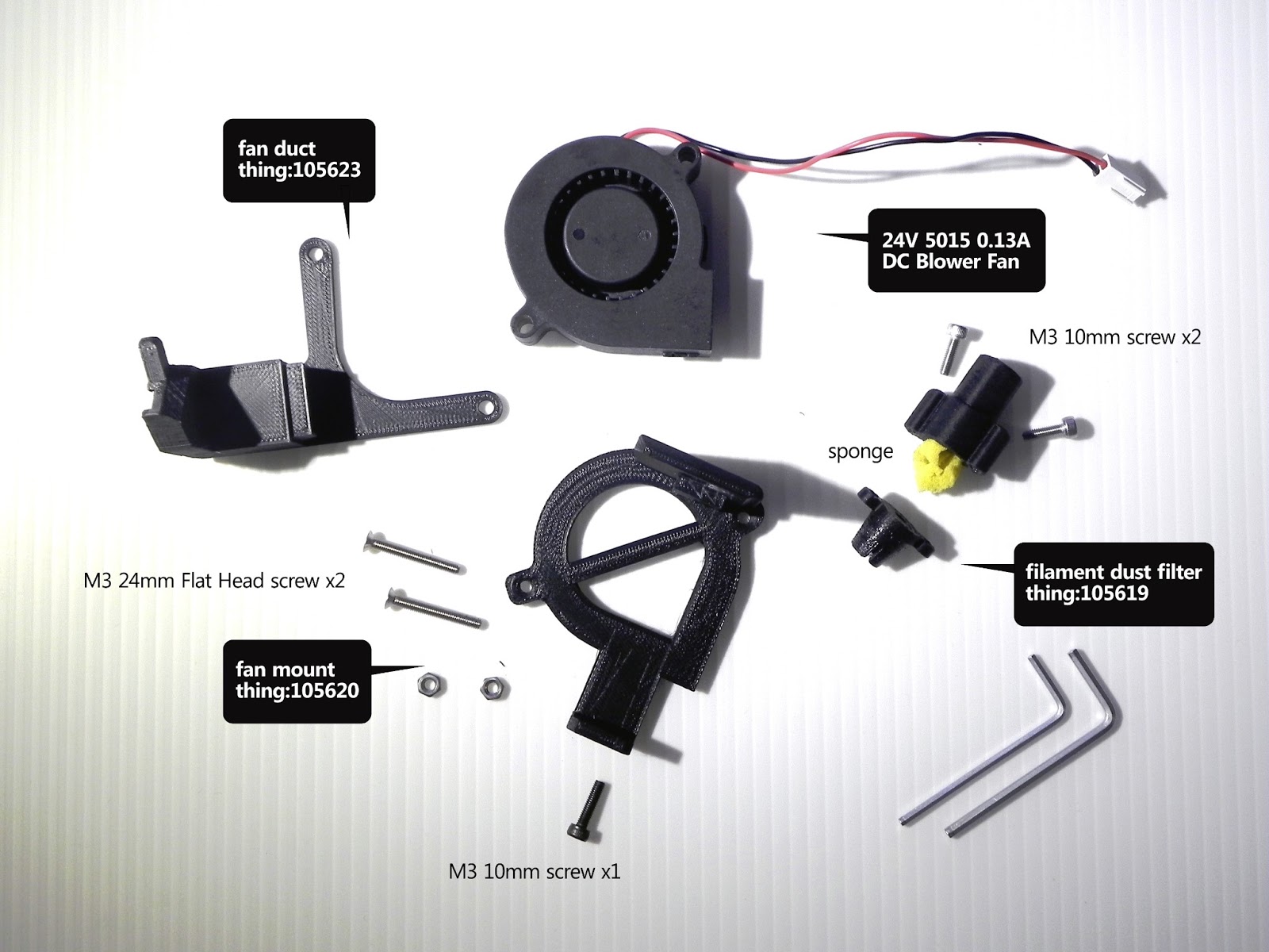
其次是準備改裝所需的物件,一共包含一個鼓風機,一個6P的切換器,以及三組要預先列印的構件。
(A) 24V 5015B 0.1A 鼓風機
24V 5015B 0.13A DC blower fan
改裝 R2 所使用的風扇部分,我是購買相似規格(淘寶連結)
代表的是 24V 尺寸 50 x 50 x 15mm B是滾珠軸承
原因無它,由於這個額外的風扇是吃 DUAL / R2X 右噴頭的風扇電力
所以風扇應該是沿用原本右噴頭風扇的規格
滾珠軸承的好處是,壽命長,較油封軸承耐髒耐灰塵(推薦!)
 |
| (單價18 RMB)寄出約兩天可收件 順豐到付運費(兩個)是168元 |
(B) 6P三切開關
顧名思義,這個元件具有六個 PIN 腳(兩兩一對共有三組),按鈕為兩段式
中間的部分是輸入端的線路,主要是接從主機板供應的風扇電力(一紅一黑)
另外兩側代表兩個輸出的線路,透過按鈕的切換選擇輸出到右噴頭風扇,或是左側側吹風扇

 |
| 這個電子零件是在光華商場的電子地下街[源達]所購買 單價一個 10 元,需要基礎焊接的技巧 |
(C) 3D Printed 物件_A
http://www.thingiverse.com/thing:105620
基於 Replicator 2 build plate fan mount 設計做修改
改變之處:
(1) 厚度由 12 mm 修改為 5 mm
(2) 固定方式改為 M3 平頭螺絲(皿頭螺絲/Flat Head Screw)x 2
 |
| M3 FLAT HEAD SCREW 24mm 皿頭螺絲,單價20元 M3 10mm 螺絲,單價10元 |
(D) 3D Printed 物件_B
http://www.thingiverse.com/thing:105623
基於 Replicator 2 Fan Duct replacement 設計做修改
改變之處:
(1) 風扇接口的尺寸進行微調(避免組裝失當而產生碎裂)
(2) 修正螺絲鎖孔位置,以免組裝歪斜(列印過程中撞到物件)
(3) 固定方式採用圓孔,非原本的吊掛式(避免列印過程中掉落)

(E) 3D Printed 物件_C
http://www.thingiverse.com/thing:105619
基於 Replicator 1 - 2 - 2X Filament dust filter 設計做修改
改變之處:
(1) 塑料導管口徑修正
(2) 與噴頭端口徑修正

[組裝成品]


德國建築師 Benjamin Dillenburger 和 Michael Hansmeyer 最近在兩個地方(Materializing Exhibition in Tokyo 和 Swiss Art Awards 2013 in Basel, Switzerland),發表了一個 1:3 scale 的空間原型。

這個名叫 "Digital Grotesque" (數位圖騰)的作品,使用 3D Printer 去建構一個瘋狂的空間圖騰。這些複雜
的圖騰,是由單元透過一種基於不斷分割再分割(細分|Subdivision)的演算法所設計、大量生成。設計師基於其複雜性,在這個空間內決定使用八千萬(80,000,000)個面來操作、詮釋。
grotesque*[grәu'tesk]
n. 奇異風格, 怪異圖案
《源自義大利語“洞穴 (的畫) ”的意思; 指常出現在洞穴中以怪獸為題材的畫》
<<形容詞>>
a. 奇怪的, 可笑的


最終是以 3D Printed sandstone 材料的方式,透過 VoxelJet 以0.14 mm的解析度,製作出一個長 1.2 米、寬 1.15 米、高 0.6 米,重達 350 公斤的作品。
The room is then 3D printed in sandstone on a VoxelJet with 0.14 mm resolution. It is 1.2 x 1.15 x 0.6 meters and weighs 350 kg.


來自設計者的解說:
在 Digital Grotesque 這個作品裡,我們探索使用簡化的手法、一種接近於極簡主義者的狀態,然後超越理性,尋求設計上的新淺力。
受自然界裡細胞分裂過程的啟發,我們發展出一套不斷進行分裂和轉形的演算法,其基本形源自於一個再簡單不過的方盒。儘管規則是如此簡單,世界的形式以不同的尺度來呈現其複雜性: 裝飾與結構、 秩序和混亂,異來和未熟悉:一種數位的怪誕。
The designers explain:
In the project Digital Grotesque we explore the new potentials of digital design using a reduced, minimalist approach that nonetheless transcends rationality.Inspired by the natural process of cell division, we develop an algorithm that iteratively divides and transforms the initial geometry of a simple cube. Despite simple rules, a complex world of forms arises at multiple scales: between ornament and structure, between order and chaos, foreign and yet familiar: a digital grotesque.


一比一真實尺度,一個完全閉合的 3D Printed 空間,將於七月22日發表。
更多的圖像與影片和請參考內文中的連結。
The 1:1 scale, fully enclosed, entirely 3d printed room will be revealed on 22nd July.
Check out more images of the prototype and a video of its construction below.
MakerWare 2.2.0 現在開始 開放下載。這個功能強大的軟體能夠幫你轉化 3D 設計變成可列印的物件,是一個關鍵必要的工具(go-to tool),也是 MakerBot 3D 環境裡,不可或缺的一環。這個版本裡最大改變是強化了自家的切層引擎-MakerBot Slicer。
我們改善了物件在懸空狀態下使用支撐材料的方式。同時,我們建構了全新的底層型態(更好剝離);此外也改進了細緻部分的掌控、物件填充的方式,以及許多的地方。我們來細看吧!
MakerWare 2.2.0 is now available for download. This powerful software is your go-to tool for translating 3D designs to printed objects, and an integral part of the MakerBot 3D Ecosystem. Here is a behind-the-scenes look at the major improvements we've made to the MakerBot Slicer, our slicing engine, with this release.
We have improved support material for objects with overhangs. We have all new rafts that are easy to detach. We have better handling of narrow features, new infill patterns (cats included), and so much more. Let’s dive in:
功能更強的支撐模式
這是 Laurana,一個義大利文藝復興時期雕塑家 Francesco Laurana 的作品,現在呈現給您 3D printed 的版本。在下圖之中,你將見到支撐結構的不同版本(左為 MakerWare 2.1.0),同時見識到新版的改進之處(右為 MakerWare 2.2.0)。支撐材料(Support structure)是 MakerWare 對一個 3D model 進行額外修正的功能,強化物件使它能夠列印懸挑的部分。舉例而言,如果少了支撐的結構,Laurana 的 Romanesque nose 將會因為本身的重量掉下來。新版的 MakerWare 提供更聰明的計算,讓支撐結構現在只出現在必要的位置。我們同時也改變了支撐材料的生成樣式,這一切只是為了讓它更容易在最後被剝離。整個物件將會使用更少的材料,更快被印製出來。
IMPROVED SUPPORT
Meet Laurana, a 3D printed version of a bust by Italian Renaissance sculptor Francesco Laurana. In the pictures that follow, you’ll see support structures generated using the old version of the MakerWare 2.1.0 (left), and how this has been improved in the new release, MakerWare 2.2.0(right). Support structures are extruded materials that MakerWare can add to a 3D model in order to reinforce objects with overhangs. For example, Laurana's Romanesque nose would droop under its own weight without support material. The new version of MakerWare is much smarter about generating supports only where they are needed. We've also changed the pattern of support material, so it's much easier to break away. Objects use less plastic and print faster than ever.

更佳的底層模式
我們同時也讓 MakerWare 2.2.0 具備了更好用的底層模式。底層(raft)是用擠出的塑料建構出一個厚實的基礎,幫助要列印的物件能夠牢牢地固定在工作平台上,好讓它維持水平與安全。我們新版所建構出的底層將變得更容易被剝離,產生一個更平滑的底面。下圖是我們所列印的一個齒輪培林,從它第一層的細部可以見到這項功能被我們改良到多麼好用。
IMPROVED RAFTS
We've also equipped MakerWare 2.2.0 with improved rafts. A raft is a thin foundation of extruded material that helps your object stick to the build plate during a print, keeping it level and secure. Our new rafts detach more easily, creating a smoother bottom surface. We printed a gear bearing to show how well our new rafts print on objects with detailed first layers.

改良的細節控制
早期的 MakerWare 版本有時會突發性的在一些細部的地方遺失掉一些細節;這將不會再發生了!MakerWare 2.2.0 提供了最好的細節控制。下圖中,你將看到新版的 MakerWare 無接縫的列印出單層的薄殼手鐲(bracelet)。
IMPROVED NARROW FEATURE HANDLING
Previous versions of MakerWare occasionally missed details on thin or narrow features. Not anymore: MakerWare 2.2.0 offers the best handling of narrow features. Below, you can see how the new version of MakerWare seamlessly printed a single-walled bracelet.
 |
| http://www.thingiverse.com/thing:13505 |
下週推出:新的填充方式與更多功能
下一週,我們將會重點發表 MakerWare 2.2.0 的新功能,包括一個新的填充方式(如下圖所示,一種像貓的輪廓的圖騰)。如果要開啟這個新的填充方式,只要創建一個新的 Profile,並且將[sparseInfillPattern]參數從[hexagonal]設定為[catfill]即可。
NEXT WEEK: NEW INFILL PATTERNS AND MORE
We'll be highlighting additional new features from MakerWare 2.2.0 next week, including new infill patterns like the "catfill" pattern featured in the picture below. In order to turn on cat-shaped infill, just create a custom MakerBot Slicer profile and change the "sparseInfillPattern" setting from "hexagonal" to "catfill"

我們今天也同步發表了最新的韌體 7.3.0。這次的版本包含了一些改進,以及一些問題的修補,包括在列印過程中置入了自動暫停的機制,好讓使用者可以進行塑料更換的動作。敬請留意我們的更新,並且別忘了下載我們的最新版本。我們很樂見新版的 MakerWare 2.2.0 如何改善你的列印方式,任何列印前後的改變照片或是建議都歡迎寄到我們的信箱。下方是關於這次新版本的功能說明。
We"ve also released Firmware 7.3.0 today. It contains a few improvements and bug fixes, including an automatic pause for changing filament colors during a print.Stay tuned for updates, and be sure to download the full release today. We’d love to see how MakerWare 2.2.0 improves the way you print, so send us your before and after photos and any feedback to thoughts@makerbot.com.
Click below to see the full MakerWare and and firmware release notes.
MakerWare 2.2.0 新特色
New features in MakerWare 2.2.0
- 改良的預設列印設定值
Improved default print settings
- 高解析度列印由原本的 Skeinforge 改為 MakerBot Slicer 切層引擎
The high-resolution default now uses MakerBot Slicer instead of Skeinforge
- 一些 MakerBot Slicer 的改進之處:
A number of MakerBot Slicer improvements:
- 更容易移除的底層
Easy-to-remove rafts
- 更精簡的支撐結構
More minimal support
- 容易剝離,波浪狀的支撐結構
Easy-to-detach, wavy support pattern
- 對於外部輪廓(脊線)更好的掌控(詳見案例)
Better handling of external spurs (as seen in the Stretchy Bracelet)
- 從表面和第一層移除掉對角線
Removing diagonal lines from surface walls and first layers
- 更柔順平滑的演算法
New smoothing algorithm
- 更好的跨距列印
Better Bridging
- 更多的填實方式(預設方式為六角形,其他模組可以在自訂檔中設定)
Multiple infill patterns ("hexagonal" is the default; other patterns can be selected in custom profiles)
- 添加了大量的新實驗設定。預設狀態下是關閉的,可以在自訂檔中開啟。詳見相關設定細項。
A number of new experimental settings have been added that are turned off in the defaults, but can be turned on in custom profiles. See the custom profile support page for specifics.
- 動態的速度計算
Dynamic speed calculations
- 內部填實(此功能是以單線路徑的來回擠出來填滿線段間的縫隙,特別是當輪廓線之間存在比單線寬度還細的空間時)
Internal spurs(Internal spurs are single lines of extrusion used to fill the gap between outlines when that gap narrows to a single extrusion width.)
- 間隙填補
Backlash compensation
- 下架的 Skeinforge 被設定為預設自訂檔之一
A new Skeinforge default profile has been added
 |
| [Make]>[Profile]>[Skeinforge Defaults] |
- 用戶可以選擇背景(skybox)的圖示為"subtle"(見下圖)
Users can choose from a subtle skybox option
- 現在可以輕易地設定 MakerBot Slicer 自訂檔的擠出溫度
It is now easy to set extruder temperature when using custom MakerBot Slicer profiles
- 為 Thing-O-Matics 機種新增[homing]按鈕
Added a homing button for Thing-O-Matics
- MakerWare 現在起支援Ubuntu 13.04 平台版本
MakerWare now supports Ubuntu 13.04

 |
| 新版的工作環境背景可選擇[subtle]進行更換 [Edit]>[Setting]>[Skybox] |
Firmware 7.3.0 新特色
Firmware 7.3.0
- 列印時在操作面板上新增列印時間的顯示。新的操作面板上將會作[列印百分比]與[列印時間]的切換
Added print time to the interface board during prints. The interface now toggles between print percentage and print time.
- 用戶可以在列印過程中使用[Z Pause Height option]功能,在特定層置換塑料
Users can now swap filament at specific layers by using the Z Pause Height option during prints.
- LCD介面上修正了一些小字顯示的問題
Small text display bugs in the LCD interface have been fixed
- 列印中途置換塑料時,步進馬達會鎖住以避免之後噴頭位置的不對齊
During mid-print filament changes the stepper motors now lock to prevent the extruder from becoming misaligned
- 列印中的塑料置換在15分鐘之後將會切換成[冷機暫停]模式
Changing filament during a print will now timeout after 15 minutes and turn into a cold pause
- 對於加熱器有更好的錯誤處理
Added better error handling for heater errors
恭喜你看到最後!快前往 Thingiverse 網站並找出那些被大家收藏的物件,用最新下載的 MakerWare 來印印看吧!
Congrats! You read to the end. Head over to Thingiverse and find your favorite Collection of things to make with your new MakerWare download.

"團結力量大"這個諺語可以充分的表達這個PROJECT的精神,Distributed Flight Array:modular robot 模組化的機器人,六角形的外型配合單軸的螺旋槳,可以組成任何的形狀或形式。雖然每個單位能夠產生足夠的推力來離開地面,但是僅靠自己是無法像直升機那樣飛行的。然而,當數個單元連接在一起時,這些裝置演變成複雜的多轉子系統,能夠在飛行中協調平衡,並具有更多的可能性。
“The whole is greater than the sum of its parts” — a catch phrase that aptly expresses the Distributed Flight Array: a modular robot consisting of hexagonal-shaped single-rotor units that can take on just about any shape or form. Although each unit is capable of generating enough thrust to lift itself off the ground, on its own it is incapable of flight much like a helicopter cannot fly without its tail rotor. However, when joined together, these units evolve into a sophisticated multi-rotor system capable of coordinated flight and much more.
源由
2008 年的夏天,ETH Zurich 瑞士聯邦理工學院的動力系統和控制研究所,Raffaello D'Andrea 教授設想一個計畫:由單轉子機器為單位、能在地面上自行組裝,然後這些單元能共同執行一項看似不可能的任務—飛行。此模組化的飛行器要能在空中分離,然後在空中再度合體(但是必須形成另一個隨機生成的配置),然後一再地重複這整個過程。
In the beginning
In the summer of 2008, Professor Raffaello D'Andrea at the Institute for Dynamic Systems and Control at ETH Zurich envisioned an art installation consisting of single-rotor robotic units that would self-assemble on the ground and then perform a joint task that would otherwise be impossible to achieve on its own — flight. This modular flying vehicle would then break apart in the air and then repeat the process over again, but in a new randomly-generated configuration.
可行性研究
要設計和實踐這樣的系統,所面臨的挑戰非常的多。首先,我們必須確定這一個概念是確實可行。關於這個系統,我們做了一些現實面的假設,除了進行一些簡便計算方法,我們也透過裝置來建立一個線性動力學的模型,以提供一些物理動力學方面的參考。基於這一點,我們制定了一種控制策略。之後,我們模擬了這個避迴系統在各種干擾之下的狀態,這為我們之後提供了成功執行的條件,包含所需的物理需求以及一般性的理解。
Feasibility studyThe number of challenges faced in designing and implementing such a system are many. We first wanted to be sure, however, that the concept was indeed feasible. Making some realistic assumptions about the system we performed some back-of-the-envelope calculations and created a linear dynamics model of the vehicle in order to provide us with some intuition about its physical dynamics. From this, a control strategy was devised. We then simulated the closed-loop system under a variety of disturbances, providing us with a general understanding of the physical requirements needed to successfully execute the project.
2008 年的秋天,這個物理系統的設計與實現其實還只是 ETH Zurich 校園,內某個進行中的設計專案的一部分。這專案包括八位來自機械、 電氣、 軟體工程領域的研究生,以及技術人員和教員,包括我自己在內。我們的任務是為設計和構建一個具有特別功能的原型,主要需具備三個關鍵的能力:(1)對接(2)地面上的協調與移動性和(3)協調飛行。在每完成一個任務之後,我們都會反過來驗證我們的模型和控制策略,來檢測一些我們可能沒有預料到的,可能會侷限系統的變數。
Design and implementation of the physical system began in the fall of 2008 as part of a design project class at ETH Zurich.The class consisted of eight graduate-level students from mechanical, electrical, and software engineering, as well as technical staff and instructors, including myself. Our task was to design and build a functional prototype that would demonstrate three key abilities of the system: (1) docking, (2) coordinated ground mobility, and (3) coordinated flight. In accomplishing each of these tasks, we would in turn validate our model and control strategy, and likely discover limitations to the system we did not foresee.
該專案無疑是極具挑戰性的,課堂時間的約束所造成的壓力,對我們的工作而言是相當的不利。我們最初的期望,是用一套套單一的裝置來展示每個關鍵的功能,之後再來證明飛行中定位的幾種可能配置。在當時的情況下,我們的目標顯得過於遙遠,最後我們只好妥協並降低我們的門檻。2009 年(數月之後,當時這門課已經結束)的夏天,我們成功達成了這些關鍵的目標,並且開始思考這個專案最終的可行性。
The project was no doubt challenging, and the timing constraints imposed by the class did not work in our favour. Our initial hope was to demonstrate each of the key abilities using a single set of vehicles and to demonstrate coordinated flight in several configurations. Our goals were too ambitious under the framework of this class and therefore loosened our requirements. By the summer of 2009 (a few months after the class had ended), we succeeded in demonstrating each of these key abilities, and ultimately, the project's feasibility.
在上面影片的末段,你會發現這個系統面臨到的許多局限,其一是它不能控制其飛行高度(或離地面的高度)。您可能還注意到為了讓它能更輕盈以便於飛行,該階段這裝置的飛行和操控兩種能力是分開的。這主要的限制是,它無法依據隨機性的配置去做到機動性的協調。這些單元本身缺乏兩兩相互溝通的能力;就算這些變成可能,我們也還沒有任何方式可以自動生成一個適當的、滿足控制策略的配置。為了這個展示影片,當時我們替每個單位都預先設定了一個特定的配置,並設定用手動的方式來控制機器。然而,這只是整個方案裡頭,冗長的代辦清單裡的冰山一角而已。
Towards the end of the above video, you will notice one of the many limitations of the system: its inability to control its altitude (or height off the ground). You may also notice that both flying and driving capabilities were separated in order to make the vehicle lighter for flight. Its primary limitation, however, was its inability to demonstrate coordinated mobility for randomly assembled configurations. The units themselves lacked the ability to communicate on each of their sides, and even if this were possible, we did not yet have any way of automatically generating the appropriate control strategy for the assembled configuration. For our demonstration, each unit was pre-programmed for a particular configuration and the controller was tuned by hand. This, however, was just the tip of the iceberg for the long list of requirements needed to successfully achieve our final goal.
反覆的設計運算
在展示了這個系統的可行性,並讓整個設計受到專案的保護與資助之後,下一步就是真正的去實踐一個能夠機動應變的模組化系統—不論是在地面和空中。這絕對不是一個容易達成的過程;如果這麼簡單,它就不會被視為是一項研究。這裝置在完成目前的設計之前,還存在著另一個修正的版本,是我們先前創建出來的。
Design iterations With the design project class under wraps, and feasibility of the system demonstrated, the next step was to engineer a truly modular system capable of coordinated mobility — both on the ground and in the air. This was by no means a straightforward process; if it was, it wouldn't be considered research. One additional revision of the vehicle was created prior to arriving at the current design.
 |
| Proof-of-concept, completed July 2009. |
 |
| Revision 1, completed June 2011. |
 |
| Revision 2, completed June 2012. |
在一號修訂版本的設計中,我們主要的目標之一是整合操控與飛行的能力。這需要我們去重新思考整個機殼,並設計出重量與推進力的比例關係。雖然乙酯聚丙烯泡沫(ethyl polypropylene foam)所做出來的機殼重量很輕,機械性也達到足夠的強度,但是在概念階段裡很難放在製造流程裡的。於是,我們切換到不同的材料進行測試。我們選擇改為構建出可被鐳射切割的乙縮醛塑膠(acetal plastic)機殼,搭配更高輸出的飛行器馬達以及一個全新設計的螺旋槳。這一種堅固的機殼很容易被生產製造,並且在達成控制性的前提下,它還能具備充足的推進力。但是我們未能考慮到機殼的剛性和轉子製造變異性。完成一號修訂版本的設計,並且生產幾個單元之後,我們發現機殼中的振動是源自螺旋槳所造成的空氣湍流,主因是控制板上的速率陀螺儀感應器受到螺旋槳電流的滲入,因此更改為避迴電路控制是必要的改進。
In designing Revision 1, one of our major goals was to integrate both driving and flying capabilities. This required us to rethink the mechanical chassis and to design with a sufficient thrust to weight ratio in mind. Although light-weight and mechanically robust, the ethyl polypropylene foam chassis we used in the proof-of-concept vehicle was difficult to manufacture and our experience led us to switch to a different material. We opted instead for constructing the chassis out of laser-cut acetal plastic, a higher-powered flight motor, and a new propeller. This resulted in a very robust chassis, which was easy to fabricate in-house, and it provided sufficient thrust for the purposes of lift and control effort. What we failed to consider, however, was the stiffness of the chassis and manufacturing variability of the rotors. Only after completing the design of Revision 1 and producing several units did we discover that the vibrating modes in the chassis caused by aerodynamic turbulence from the propellers saturated the onboard rate-gyroscope sensors, which was needed for closed-loop control.
六個接合面都具備傳輸溝通的能力,也是這一個修訂版本中很重要的一個里程碑。我們成功地安裝紅外收發器到每個連接介面上。然而,我們後來發現進行實驗時,紅外線系統會與我們裝置環境的 3D 運動捕獲系統(用於地面測量)發生干擾,由於它使用類似頻率的紅外燈來照亮,會被辨識為跟蹤的標記。
It was also important in this revision to demonstrate communication on each of its six sides. We successfully accomplished this using infrared transceivers mounted to each connection interface. However, we later discovered interference issues when conducting experiments with our vehicle within the environment of a 3D motion capture system (needed for ground truth measurements), which uses a similar frequency of infrared light to illuminate markers that it tracks in order to estimate the pose for the object of interest.
另外我們也需要縮小電子設備的大小,這樣它才能納入提供保護的機殼之內。我們當時看到彈性印刷電路板的技術,對於這個技術的可行性產生了動機,並關注在這項計畫裡。當真正進入到主機板的生產時,在較小的數量上,這種服務所需的時間對我們而言實在太長了—我們希望能快速生產出原型,並放到設計裝置上進行測試。因此,我們不得不為一個標準的印刷電路板重新設計整個部分。
On top of this was the need to shrink the size of the electronics such that it would fit within the protected volume of the chassis. We were motivated by recent manufacturing possibilities in creating flexible printed circuit boards, and locked on to this scheme. When it came around to producing the boards, however, the lead-time for such services in relatively small quantities was much too long for our requirements — we wanted to be able to prototype and have a quick turn-around on our designs. We therefore had to redo parts of the design for a standard printed circuit board.
當系統第一次使用 3D 運動捕獲系統進行試飛時,透過回傳的測量訊息,我們得到了一些具建議性的資料。這些測量是非常精確和相對快速的,我們可以利用電路板上的功能直接估計問題,並只專注于這些問題的控制。事實上,我們主要在處理兩個項目:(1)如前面所述,從 3D 運動捕獲系統發出的紅外燈,會造成單元相互溝通時的干擾;(2)測量資訊 (或控制資訊) 在操控的前提下需要以無線的方式進行傳送,而在一般的發展(使用 WiFi)下,會產生大量的延遲和資料包的遺失。
There was also the suggestion to first fly the system using a 3D motion capture system for measurement feedback. Since these measurements were very precise and relatively fast, we could by-pass the onboard estimation problem and focus only on the control problem. This, in fact, worked against us for two major reasons: (1) as described before, the infrared light from the 3D motion capture system interfered with inter-communication; and (2) measurement information (or control information) needed to be transmitted to the vehicle wirelessly for control purposes, which at the time of development (using WiFi) generally incurred a lot of latency and packet loss.
有很多需要重新設計的項目,許多存在於假設的階段,而且有著要將研究出版的壓力。在一號修訂版,我們試圖在一次跳過太多的障礙,導致我們得到一個處於半工作狀態的系統—優化操作條件下,才能具備功能性,但大部分的時間是無法正常運作的。然而,我們也因此學到了許多,特別是我們集中注意力在設計而忽略的部分。這奠定了二號修訂版的方向,重點主要在開發地面上的作業。
There was a lot that needed to be redesigned, a lot that was assumed, and there was pressure to get research publications out. In Revision 1, we tried to jump over too many hurdles at once and what we delivered was a semi-functional system — functional under optimal operating conditions, but failed to work most of the time. However we learned many things, in particular it focused our attention on parts of the design that we overlooked. This laid the ground work for Revision 2.
在二號修訂版,我們重新設計的機殼以及提供推力的單元(螺旋槳和飛行電機)。一切從零開始,但保留的大部分電力和電子控制裝置。使用了一些製造技術上的最新研究,機殼在這個階段開始使用 3D 列印的技術,使我們能夠以很少的製作限制來進行設計,同時擁有相對快速的應變時間。第一個因素非常重要,這使得數個元件可以緊密的整合在一個單位內。第二個因素使我們能夠快速測試設計,不斷地重複這個流程是免不了的。
In Revision 2, we redesigned the chassis and thrust generation unit (i.e. propeller and flight motor) from scratch, but kept most of the power and control electronics the same. Using some of the most recent advances in manufacturing technology, the chassis was 3D printed this time around, enabling us to design with very little fabrication constraints and has a relatively quick turn-around time. The first factor was very important because of the number of tightly integrated components held together within a single unit. The second factor enabled us to quickly test a design and re-iterate as necessary.
這一次,我們有系統地穿過每個階段的設計。新的飛行發動機和螺旋槳被測試以確保它產生足夠的推力,並減少對機殼所產生的振動,使用的還是一號修訂版用的速率陀螺儀感應器。我們沿用一號版的電子單元,並用上兩組裝置,在水平向度上裝載兩個單位,測試避迴電路中沿著單一軸向旋轉的模式。這單獨的測試需要反覆幾次修改機殼,最終得到理想的版本。
This time around, we stepped through each phase of the design systematically. The new flight motor and propeller was tested to ensure that it produced a sufficient amount of thrust and produced little vibration within the chassis, which we tested using the rate-gyroscope sensors from Revision 1. Using two units and electronics from Revision 1, we tested the closed-loop behaviour around a single axis of rotation by mounting the two units on a horizontal pivot. This alone required a few iterations of the chassis, which in the end we managed to get right.
忽略相互溝通的問題,我們為了飛行的需求,埋首建造了六個完整的裝置單元。在今次的修訂版本中,我們展示了不同的配置下的協調飛行。飛行控制器是提前計算好的,並以無線方式在飛行前發送到每個單位。
Ignoring the intercommunication problem, we ploughed ahead and constructed six complete units for flight. In this revision, we demonstrated coordinated flight for a variety of configurations. The flight controller was computed ahead of time and sent wirelessly to each unit prior to flight.
機殼和推力的問題解決之後,於是我們開始著手各單位的操控和通訊能力。後來,我們重新設計通訊的方式,採用一個硬線的介面而不是紅外線連結,並利用母線的設計解決了我們在第一個版本中大量的通信線路。在下一節中有詳細的說明。
Knowing that the chassis and thrust generation unit was sound, we then went ahead and integrated driving capabilities and intercommunication into the units. In terms of the latter, we redesigned the intercommunication scheme, employing a hard-wired interface instead of an infrared wireless link and utilized an electrical bus to clean up the mess of communication lines we had in Revision 1. A detailed description is given in the next section.
由下而上的設計
每個單位使用單一 32 位元 72 MHz 的微控制器,控制嵌入的感應器、 執行器和通訊週邊設備等的所有介面。同一個微控制器還拿來用於執行所有控制所需的相關計算—沒有任何電路之外的計算。可互換的無線模組 (WiFi,或專有的跳頻擴頻) 允許我們與每個單元連線(例如遙測和下使用者命令);在這樣的情況下,我們可以配合外部感應器的使用(例如 3D 運動捕獲系統),資料將可以通過此無線連結發送到各單位。
Designed from the ground upEach unit uses a single 32-bit 72 MHz microcontroller to interface with all of the onboard sensors, actuators, and communication peripherals. The same microcontroller is also used for performing all of the computation necessary for estimation and control — there is no computation that is performed offboard. An interchangeable wireless module (either WiFi or proprietary frequency hopping spread spectrum) allows us to communicate with each unit (e.g. telemetry and user commands); in the case where external sensors are used (e.g. 3D motion capture system), the data can be sent to the units over this wireless link.
 |
| Components of the DFA. Each unit uses a single 32-bit 72 MHz microcontroller to interface with all of the onboard sensors, actuators, and communication peripherals |
 |
DFA 的元件
每個單位使用單一 32 位 72 MHz 微處理器連接
電路上所有感應器、 執行器、 和通信週邊設備
|
大多數航空飛行器是採用三軸速率陀螺儀為標準,用於測量本體速度角,以及估計裝置在飛行中的狀態。紅外距離感應器用來測量一個單位到地面的距離。不僅使用此感應器來估算裝置的高度,如果單位間分享他們高度的測量值,它們可以在飛越平坦的表面上空時,估計裝置的傾斜度。
Standard on most aerial vehicles is a 3-axis rate-gyroscope, which is used for measuring body angular velocities, as well as estimating the attitude of the vehicle in flight. An infrared distance measurement sensor is used for measuring the distance of a unit to the ground. Not only is this used for estimating the altitude of the vehicle, but if units share their distance measurements with one another they can also estimate the vehicle's tilt when flying over a flat surface.
我們同時為每個裝置設計了帶有磁性的介面,位於它的六個接面上。這允許一個裝置以被動的方式,與它周邊的裝置自動對齊。不過,這樣的連接強度其實不是很強。這樣的設置是必要的,因為它清楚地表明,個別單位之間需要進行合作以實現飛行的訴求—如果沒有它,裝置會在起飛前就自行斷裂。要成功地完成這個任務,飛行控制的策略必須是儘量減少飛行期間,裝置相互之間連接所產生的剪力。
We have designed each unit with magnetic interfaces, located along each of its six sides. This allows a unit to passively self-align with its connected peers. The connection strength, however, is in fact not very strong. This was intentional, as it clearly demonstrates the need for cooperation between individual units in order to achieve flight — without it, the vehicle would simple rip itself apart before take-off. To successfully accomplish this, the flight control strategy must minimize the shear forces occuring between interconnected units during flight.
三個黃金推針也建構在每個裝置的六個面上。與磁鐵一起整合運用,此介面的應用類似於蘋果的 MagSafe 電源連接器,不同處在於它提供了鄰近裝置之間的通信。這一點,我們開發自己的網路來處裡裝置相互間的溝通,以及路由的資料、時間同步、資訊融合技術等的演算法,以適用於一個資源有限的嵌入式系統。此外,裝置能夠在平面的一個距離內使用紅外無線收發器,其目的主要為了裝置間的自行組合。
Also located on each of its six sides are three gold push-pins. Together with the magnets, this interface behaves similarly to the Apple MagSafe power connector, except that this interface is used to provide a means for hard-wire communication between neighbouring peers. With this, we developed our own network layer to handle inter-unit communication, as well as algorithms for routing packets, time synchronization, information fusion, etc. on a resource limited embedded system. Units are also able to communicate with one another in plane at a distance using infrared wireless transceivers, which is primarily employed for self-assembly purposes.
 |
| Distributed Flight Array: Self-assembly. |
每個單元搭配三個全方位轉輪,使它在地面上的移動具有高度的機動性,並能在群聚的狀態下一起移動。使用 3D 印表機技術來列印全方位轉輪,一體成型的優點讓它不需要裝配任何的元件。
Each unit is equipped with three omni-directional wheels, allowing it to move on the ground with a high degree of maneuverability and to be able to move when assembled together. One of the nice things about using 3D printer technology is that the omni-wheels could be printed as a single piece, without having to assemble any components.
定位在裝置中心的是一個固定的螺旋槳,能夠產生足夠的推力,將單一的裝置拉升到距離地面一定的距離。所有裝置在物理性基本上都一樣,除了螺旋槳的設計;部分是順時針方向,一些是逆時針方向旋轉—如此設計能夠取消在飛行中的空氣動力力矩。最後,需要一個高容量的鋰聚合物電池,用來提供所有的電子產品和裝置的電源。
Positioned at its centre is a fixed-pitch propeller, capable of generating enough thrust to lift a single unit off the ground. All units are physically identical except for the handedness of its propeller. Some are clockwise and some are counterclockwise — this is needed in order to cancel out the aerodynamic torques in flight. Finally, a high energy-density Lithium-Ion Polymer battery is used to power all the electronics and actuators contained onboard.
協調飛行
各單位可以在地面上移動、組裝、組成 adhoc 網狀網路(以便於與其他裝置交流),但在分散式飛行陣列中最突出的特色,是無限制數量下進行配置與應變的飛行能力。
Coordinated flight
The units can move around on the ground, self-assemble, generate an adhoc mesh network in order to communicate with one another, but the most striking feature of the Distributed Flight Array is its ability to fly in an unlimited number of configurations.
還記得這些裝置間是靠著微弱的磁鐵組合。因此,每個裝置被要求飛行中的控制性,以減少群聚單元之間的剪力。最令人驚訝的是,單位之間不一定需要在飛行過程中與另一個傳遞訊息。
Recall that the units are being held weakly together with magnets. Thus, each unit is generating the appropriate control effort necessary to keep the vehicle in flight while minimizing the shear forces between individual units. What is most surprising is that the units themselves do not necessarily need to communicate with one another during flight.
飛行狀態下,單一裝置唯一需要傳遞的資訊是該裝置的位置,對應到整群裝置的中心位置。這可以被計算出來,如果每個裝置單元知道其物理配置。為了確定在這個訴求上,每個裝置可以偵測自身,每個單位可以通過共用相應的資訊,運作與鄰近裝置的關係。通過網路的轉發,這些資訊可以讓每個裝置到達對的物理配置,就如同一個人如何建立自己的家族。
The only information that a unit needs for flight is its local sensor data and its position with respect to the vehicle's centre of mass. This can be computed if each unit knows the physical configuration of the vehicle. In order for a unit to determine this on its own, each unit can work out its relation to neighbouring units by sharing appropriate information. By forwarding this information around the network, each unit can arrive at the physical configuration of the vehicle, much like how one might establish his/her family tree.
基於一個嚴謹的設定,在設計這些機殼、感應器資訊時,必須考慮到提供一個單位與裝置的傾斜與海拔高度的粗略估計能力。知曉單元對群體中心的位置,它得以對任何擾動做出所需的適當應對與控制。我們避免使用線性二次型調節器或其他最佳化後的控制策略,事實證明這樣的方法才能提供擴展的可能性。我們採用一個層疊的參數化控制器,組成物理上直觀的調整參數方式 (即閉迴電路頻率和衰變比),以提供每個向度的自由度。
Assuming a rigid body for the vehicle, which was taken into account when designing the chassis, local sensor information provides a unit with a rough estimate of the vehicle's tilt and altitude. And knowing its position with respect to the centre of mass, it's straightforward to work out the appropriate control effort needed to counter-act any disturbances. We avoided using a linear quadratic regulator or other optimal control strategies in favour of something much more straightforward, and as it turns out the method is also scalable. We employ a cascaded parameterized controller, consisting of tuning parameter that are physically intuitive (i.e. closed-loop natural frequency and damping ratio) for each degree of freedom.
現在,它不再需要手動的方式去調整控制器的每個配置。取而代之,我們開發了自動計算任何飛行配置的裝置,會最佳化參數以達到最有效率的飛行性能。在仔細的分析並獲得各種配置參數之後,我們開發可以應用於不同尺度、放樣到不同配置下,近似最佳化控制裝置的方法。
Now, it wouldn't be reasonable to hand-tune the controller for each and every configuration. We instead developed a means for automatically computing the tuning parameters for any flight-feasible configuration of the vehicle that would result in best flight performance. In carefullly analyzing the parameters obtained for a variety of configurations, we then developed a scalable method for mapping the configuration of a vehicle to its approximated optimal control tuning parameters.
義大利公司 3ntr 發表一款新的尼龍塑料,是為 3D Printer 量身訂製的。這款 3mm polyamide 6 filament 成分是 99.9% 的 PA6 Polymer(聚醯胺 6,一種特殊的工程塑料),不參雜任何的塑化劑與玻璃纖維,剩餘的 0.1% 是肥皂,用來簡化加工。這款塑料不同於 Taulman's Nylon 具有彈性,其特性是讓列印出的材料對靜載重與活載重有更佳的對應性。
Italian company 3ntr has launched a new nylon filament developed specifically for 3d printers. This 3mm polyamide 6 filament is made up of 99.9% PA6 Polymer, no plasticizers, no fiberglass, and 0.1% soap to ease processing. It is not as flexible as Taulman's Nylon, but it is aimed to print structural parts that must be able to resist static and dynamic loads.

根據 3ntr 公司的說法,polyamide 6 的列印設定趨近於 ABS,只有列印的溫度不同(240-280°C,高於ABS的220°C),列印厚度只要設定 0.25mm 就可以得到最佳的列印結果。
此外,polyamide 6 在黏稠度上具有不同的特性(相較於 PLA 與 ABS 等常見的家用 3D Printers 塑料),該公司建議使用者使用電木([法] bachelite/[英] bakelite )或是尼龍作為底板,以得到最佳的列印效果。使用這種塑料時,並不用開啟加熱底板,在列印第一層的時候,厚度設定為標準層的 80% 就夠了。最好的列印速度是 70 mm/sec,如果要獲得最佳的附著性,速度要降為 40 mm/sec。
According to 3ntr, settings for printing polyamide 6 are similar to ABS, only the printing temps should be 240-280°C, and the best printing results can be obtained with layer thinner than 0.25mm.
In addition, Polyamide 6 has different adhesion properties from other common use plastic for 3D printers (PLA or ABS), 3ntr suggests users to use bachelite or nylon bed for the best result. And it is not necessary to heat the plate, in this case setting the first layer thickness to be 80% of standard layer is enough. The maximum advisable speed is 70 mm/sec, though the best adhesion is obtained at 40 mm/sec.

3ntr 成立于五十年代末,當時主要在生產緊身衣部件。現任的行政總裁 Davide Ardizzoia 先生是一名紡織工程師,同時也是 3D 繪圖軟體 Rhinoceros 的資深用戶(超過12年),具有電腦圖形背景,在幾家機器人和電腦控制的公司都有涉略。
"真逗趣,我們沒有使用上最新的技術 (直線電機、 雷射器、 機器人、 超聲波焊接機、 微粉化的聚合物、 熱熔系統)",Ardizzoia 說。"七年前我們一腳踩進快速成型的世界。對於這項技術的可能性實在讓我們感到驚訝,但也付出了巨額的費用"。根據 Ardizzoia 口述,一些獨立的測試者報告指出,polyamide 6 有近似於 Taulman 618 的列印特性,差別是 polyamide 6 較不容易捲曲。
3mm polyamide 6 filament 目前只有白色可以選擇。黑色尼龍仍處於調教的過程,希望能獲得一致性的結果。價格是每線軸(450克)25€(33美金,約一千台幣)。以下是一些列印的聚醯胺 6 的測試:
3ntr was established in late fifties to make corsetry parts. Current CEO Davide Ardizzoia was a textile engineer, an early user of Rhinoceros (12+ yrs), with a computer graphics background, peppered with several stages at robotics and machine control companies.
"Funny enough we end up using latest technologies (linear motors, lasers, robots, ultrasonic welders, micronized polymers, hot melt systems)", says Ardizzoia. "Seven years ago we stepped into rapid prototyping. We were amazed both from the possibilities of the technology but also from the huge costs involved." According to Ardizzoia, some independent beta testers reported that polyamide 6 has more or less same printing behavior as Taulman 618, only polyamide 6 is a little less "warpy".
The 3mm polyamide 6 filament is currently available in white color. The black nylon is still in its fine-tuning process to get consistent results. The price is 25€ ($33) per spool (450 gr).
Here are some test prints of polyamide 6:


